AMMONIA DETECTION AND VENTILATION
Ammonia machinery rooms are required to have ammonia ventilation and detection systems by code. These systems must detect low-level leaks at 25PPM and provide an audio and visual alarm at a monitored location. When a concentration of 150 PPM or above is detected, the system must provide an audio and visual alarm, and automatically turn on the emergency ventilation system. If a high level of 40,000 PPM is detected, the system must shut down all rotating equipment in the machinery room and activate the emergency ventilation system.
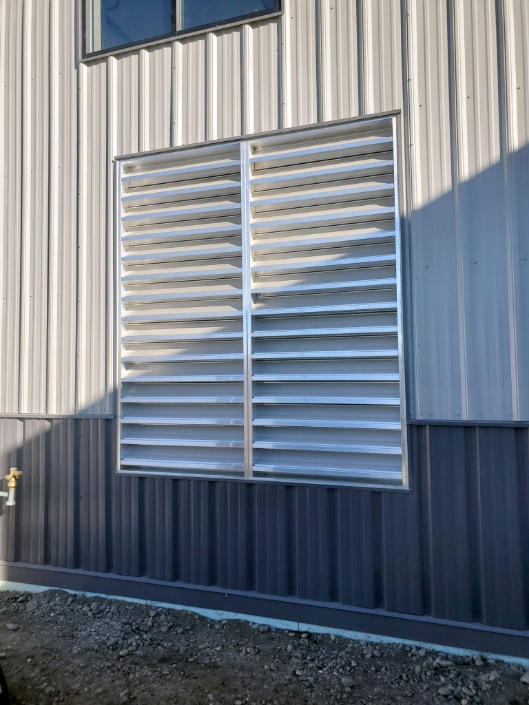
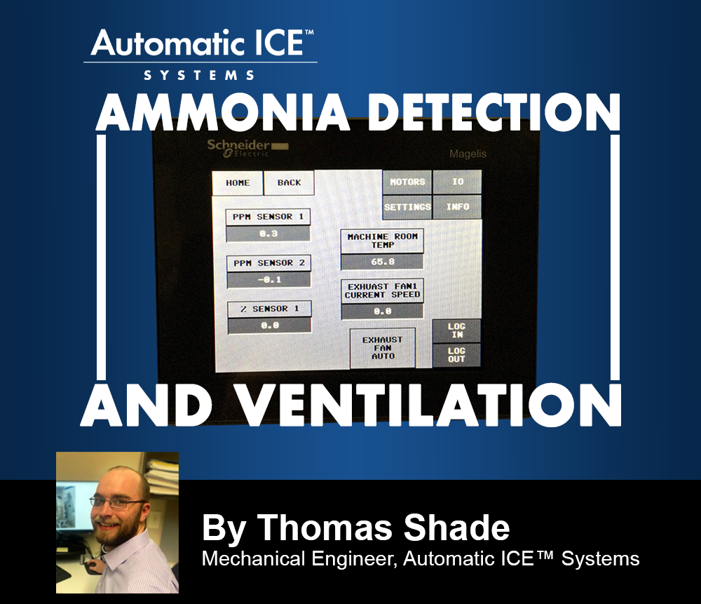
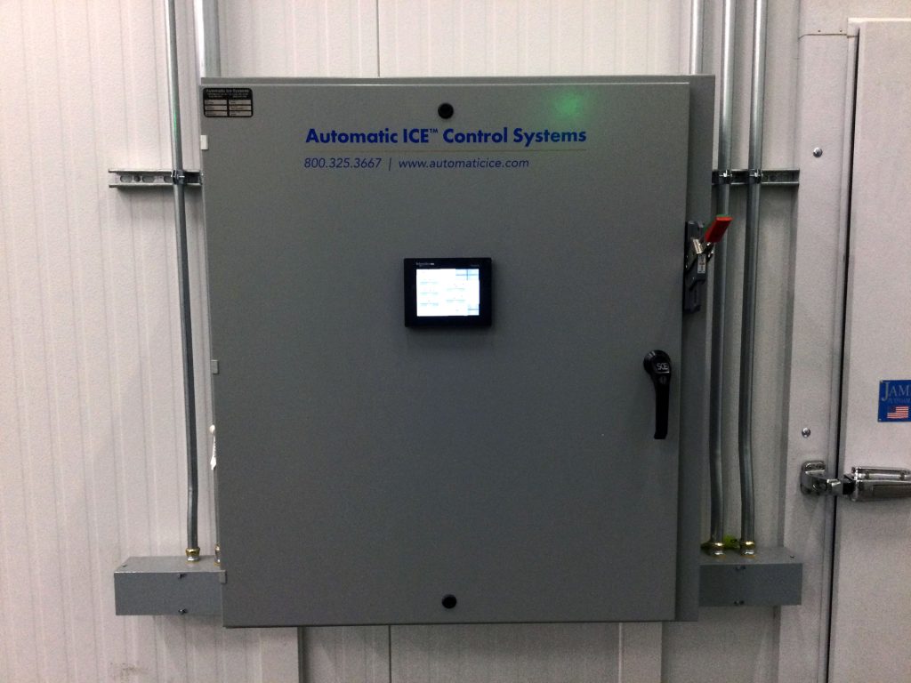
Automatic ICE™ Systems has developed our ADV system, which stands for Ammonia Detection and Ventilation. This package includes a stand-alone control panel with HMI, all required ammonia detectors, emergency ventilation fans & louvers, and King & Queen solenoid valves installed in the refrigeration system. This system will detect ammonia concentrations at all required levels and automatically enact the appropriate response. In addition to the equipment and controls, this system includes audio and visual alarms at each machinery room entrance and a door monitor that displays the ammonia PPM outside the door so operators can see the room condition before entering. The system will shut down all equipment inside the machinery room when a high concentration is reached and close King and Queen valves in the ammonia system to hold the ammonia charge in the high-pressure receiver or HPR.
An emergency ventilation system should consist of
- Emergency Ventilation
- Rooftop upblast fans
- Minimum discharge velocity > 2,500 feet per second
- Minimum 30 air changes per hour
- Non-sparking fan blades
- Fail-open air intake louvers
- Temperature Control Ventilation
- Done with emergency ventilation fans (VFD driven)
- Pulls in ambient outside air to keep room below 104°F (typical maximum allowable temperature for electrical components)
- Occupancy Ventilation
- Provides occupancy ventilation as required by mechanical code
AMMONIA OVERPRESSURE PROTECTION
AIS provides ammonia relief system design and calculations that meet all code requirements. The ammonia relief system must provide overpressure protection for all pressure vessels in the system to relieve excess pressure due to a fire or other abnormal conditions. Detailed calculations are required to determine the required discharge capacity for each pressure vessel, proper valve selection, and proper piping to ensure the maximum allowable backpressure allowance is not exceeded. The EPA can audit a plant at any time and requests to see a copy of the relief system calculation.
Relief system requirements include
- Vapor relief valves shall be connected above the highest anticipated liquid ammonia level
- The set pressure for a pressure relief device shall not exceed the design pressure of the equipment protected
- One or more dual pressure relief devices installed with a three-way valve to allow testing and repair
- Pressure relief device capacity determination due to overpressure due to external fire to prevent catastrophic failure
- Piping for relief vapor shall be determined based on the sum of the discharge capacities of all relief devices that are expected to discharge simultaneously
- Maximum length of discharge piping installed on the outlet of pressure relief devices discharging to the atmosphere as a function of allowable pressure drop
- The calculation of backpressure due to the discharge piping at the outlet pressure relief devices shall be determined using Equation 15.5.1.1.1(1) or 15.5.1.1.1(2) detailed in ANSI/IIAR 2-2021
- Pressure relief devices shall discharge vapor directly to the atmosphere outdoors
- Discharge piping shall terminate not less than 15ft above grade and not less than 20ft from windows, doors, and ventilation intakes. Termination of discharge shall be directed upward and arranged to avoid spraying ammonia on persons in the vicinity
AMMONIA SIGNAGE, LABELS, AND PIPE MARKINGS
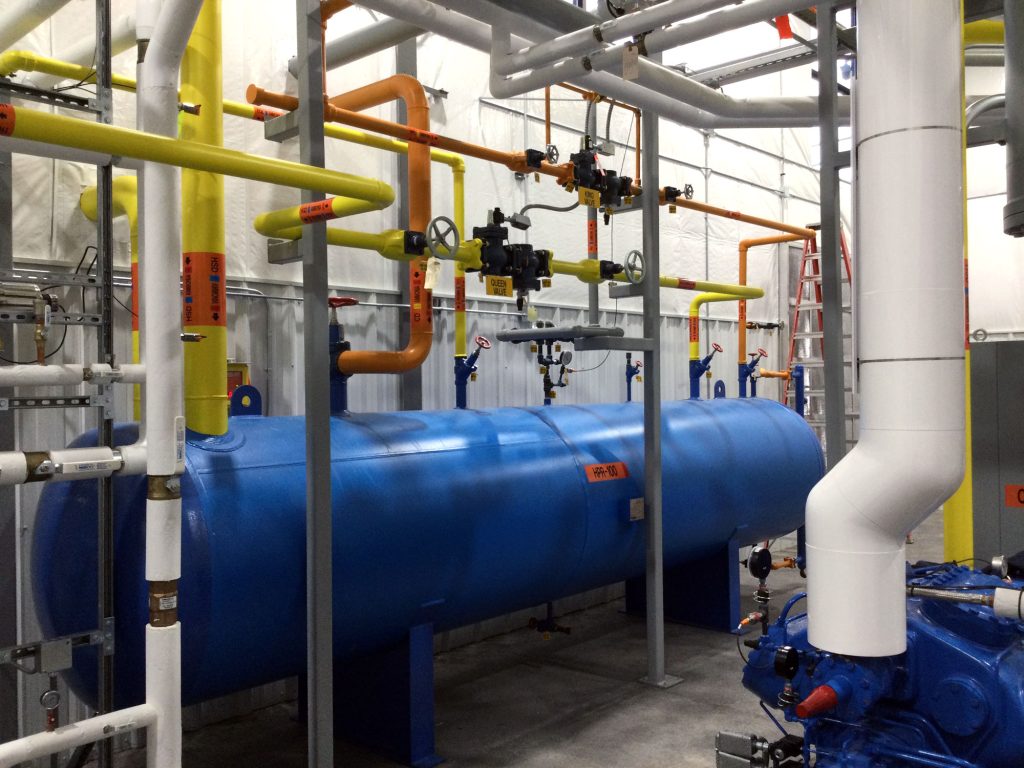
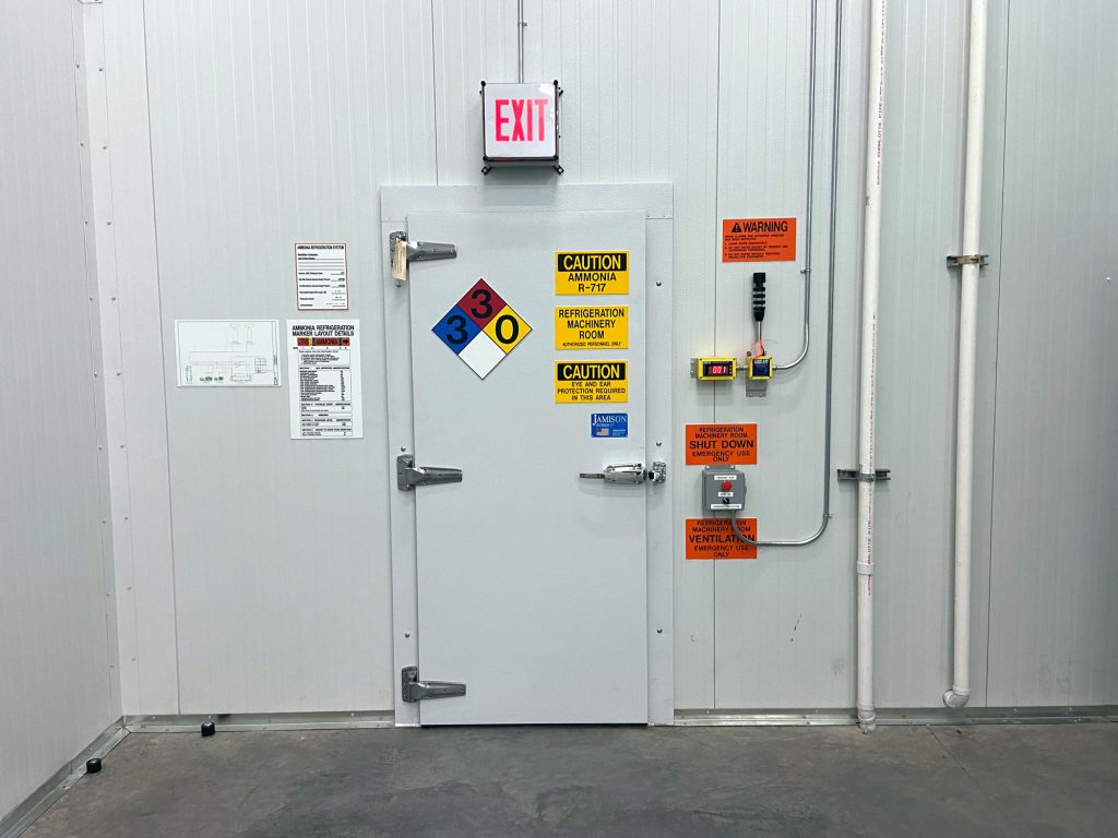
Ammonia refrigeration systems are required by code to have proper signage, labels, and pipe markings. These markings must be uniquely labeled in a manner consistent with the system documentation. Automatic Ice provides these with all new plants and can retrofit existing plants upon request. Refrigeration schematics, called P&IDs, detail piping service, equipment numbers, valve tags, and emergency shut-off valves. All piping is provided with a maker that lists the refrigerant, the physical state of the ammonia as either vapor or liquid, the relative pressure level as high or low, pipe service, and the direction of flow. These allow operators and emergency responders to identify system components accurately and quickly. Each valve in the system is given a tag with a unique number corresponding to the P&IDs. This allows the plant to write standard operating procedures, or SOPs, for routine and preventative maintenance items.
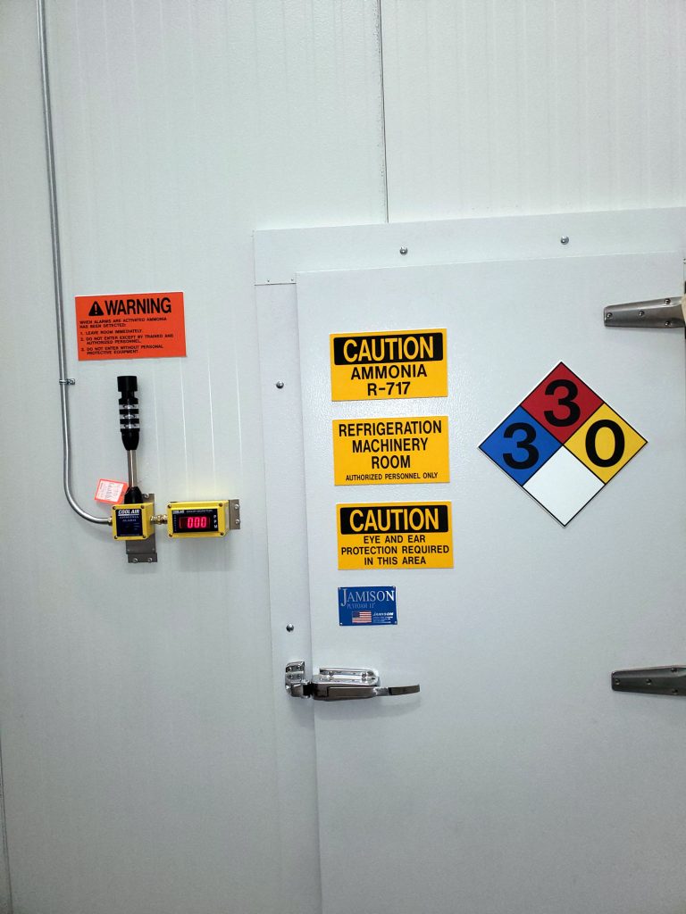
Machinery room principle and auxiliary doors are provided with the required signage indicating the Refrigeration Machinery Room, Authorized Personnel Only, Caution – Ammonia R-717, Caution – Eye and Ear Protection Required, and the NFPA ammonia fire diamond. In addition to the door signage audio and visual alarms for the emergency detection and ventilation system are provided.
AMMONIA SYSTEM DESIGN
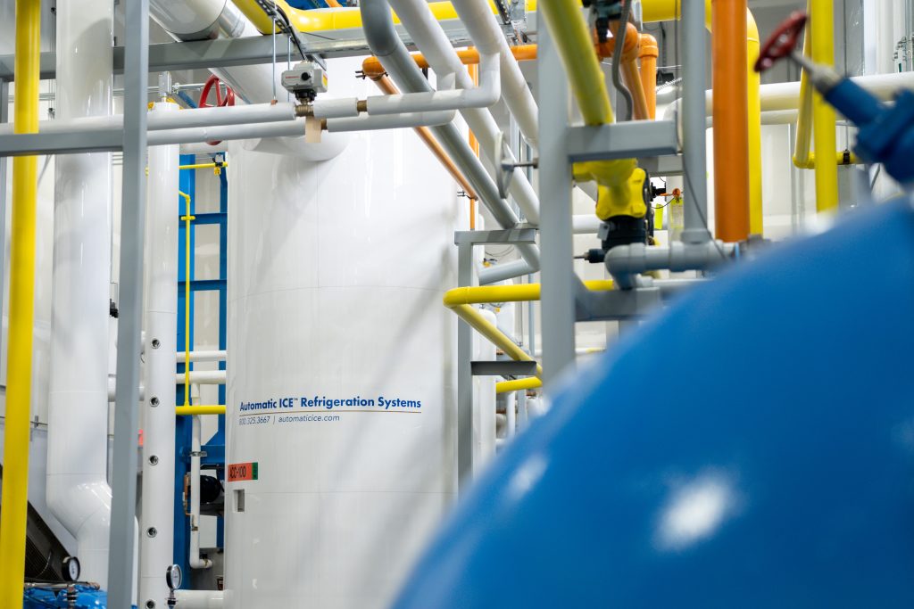
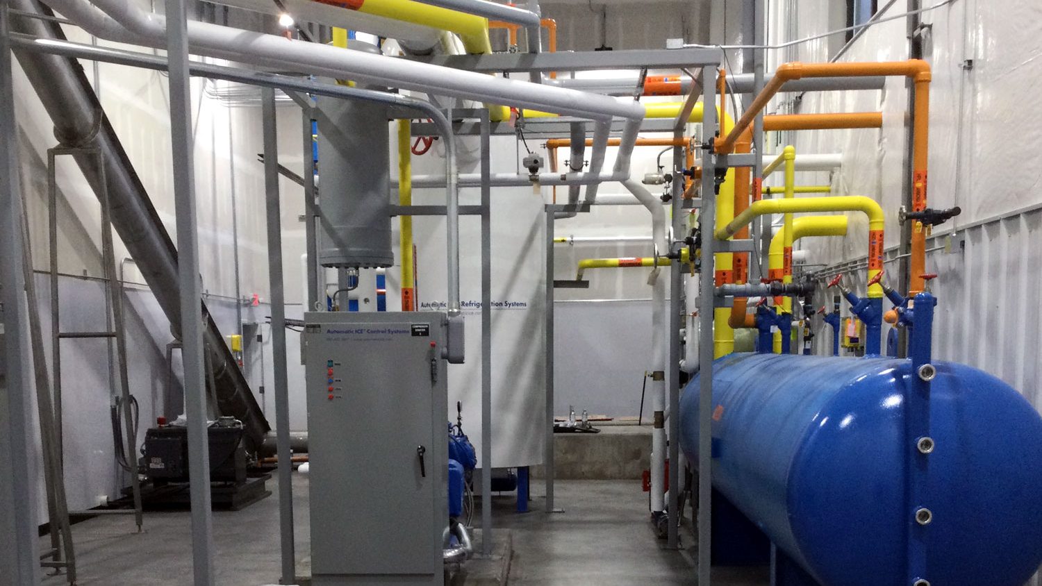
Automatic ICE™ Systems designs every ammonia system to comply with IIAR standards. This includes equipment isolation valves and pump-out valves for equipment maintenance, purge valves for removing non-condensables, oil pots to safely remove oil, and King and Queen valves for automatic isolation of the HPR in case of an ammonia leak. The accumulator vessel is equipped with a level probe as well as a high-level float switch for compressor protection. The AIS control system monitors the exact liquid level with the level probe, and can safely shut down the system before the liquid can reach the high-level cutout float switch. This allows operators to restart the system and troubleshoot while protecting the compressors.
AIS also uses a motorized control valve for the equalizer/bypass on the main suction stop valve. This allows the ice maker to bleed pressure off slowly after defrost, which prevents unnecessary liquid carryover to the accumulator.
If your company is considering growing its ice production platform, AIS can help you make the best purchasing decisions to better meet your needs today and as your company grows into the future.
